Optical to analog audio converter
The PCB I made recently was for this project that converts audio from a TOSLINK input to analog stereo.
My new TV has no analog audio outputs - only an optical one (and its speakers suck), and the “home theatre” system (a Sony DVD player with a 5.1 speaker system) accepts only analog stereo. If I bought a home theatre system I would have made sure it has an optical input, or at least “line in” inputs for the 5.1 so that I can use the amp. This little project was designed to bridge the 2 systems (with loss of audio quality).

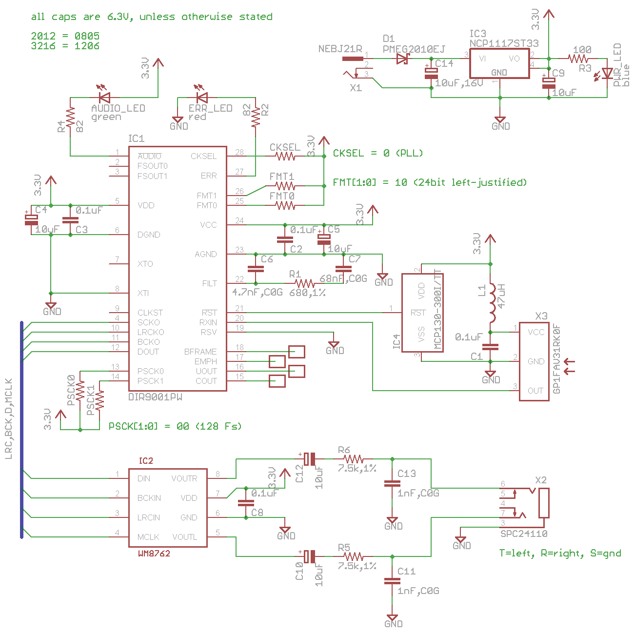
The circuit is really simple - most of the heavy lifting is done by 2 main ICs - the DIR9001 digital audio receiver and a WM8762 DAC.
Design Decisions
My design decisions are mainly driven by cost, and was largely influenced by this circuit, which just consists of the DIR9001 receiver.
The DIR9001 is the cheaper digital audio decoder, compared to the CS8416. To simplify things, I decided to use a single 3.3 V supply and the WM8762 meets this criteria. It’s a fuss-free IC that has integrated output filters. Since the output of the DAC is relative to the supply voltage, the volume might be a little on the soft side, but that’s not a big problem since it will be fed to an external amp. The fibre optic receiver has a 3 V and 5 V variant. The 3 V variant is able to withstand up to 3.6 V.
There is an on-board 3.3 V LDO regulator, as well as a Schottky diode for reverse polarity protection. The regulator accepts up to 20 V, and has a maximum dropout voltage of 1.2 V. Adding the diode forward voltage, we have a range of about 5 V to 20 V. I chose a rather large regulator that provides up to 1 A, but the circuit definitely consumes less.
Component size. SMDs are cheaper than through-hole parts, so I decided to go all SMD, which is why I required a PCB. The DIR9001 is only available in TSSOP, so it’s not like I had a choice. I prefer bigger components as my eyesight is not that good. I settled on 0805 components based on this thread on the adafruit forum.
Everybody loves blue LEDs - i just had to use one too. Blue LEDs at 0805 have a rather high foward voltage drop of about 3.3 V, which is dangerously close to the supply voltage. To be on the safe side, I used an 0603 instead, which had a VF of 2.85. The PCB footprint I used can accommodate an 0603 as well.
Since I will have 10 copies of the same PCB, I thought I’d make the design slightly more flexible. 4 pins meant for additional processing of the audio data were brought out onto solder pads, and the control pins (for settings like FMT, CKSEL) had resistors to Vcc. These control pins have an internal pull-down resistor, so if we need to set it low, the resistor is left unpopulated. DIP switches occupy space and are not necessary as the settings won’t need to be changed often nor on-the-fly.
The DAC requires a master clock, which is several times the sampling frequency. This can be obtained from the DIR9001, recovered from the optical signal. Looking at both datasheets, only 128 * Fs can be used if the DAC is to support all audio sampling frequencies. At the DAC output is a 20 kHz low-pass RC filter, whose values are derived from the active filter recommended by the datasheet.
The PCB was made to fit in a plastic enclosure I obtained locally. Since it was to be sitting behind the TV, it should be in some box. SMD components are mounted on the top side, and connectors will be mounted on the underside.

Adding RCA jacks directly to the PCB meant that I had to cut out 2 large holes for them, so I cheated a little and went with a 3.5 mm stereo jack instead. The RCA cables will then be connected via an external adapter.
End Result
I thought the final product was quite good, although the cutting of holes in the enclosure was not.

I suck at cutting holes.


The best hole that I cut was for the DC input jack.
Lessons Learnt
Depending on the DC wall wart used, the 10 uF capacitor before the regulator might not be sufficient. I tried a 12 V unregulated wall wart from Black&Decker and it didn’t work. The regulator gave an output of about 3 V (measured using a multimeter) and the DIR9001 was kept in reset state. I had to replace the 10 uF with a 100 uF.
Also, the blue LED was more towards cyan. I was expecting a darker shade of blue. I should remember to check the wavelength when I look for a blue LED next time.
The other problem which can’t be seen in the photos is that the LEDs are too bright. I calculated 15 mA for the LED current, which I think is wayy too much. Since the LEDs not used for lighting, I should probably run them at lower than 10 mA, or maybe even less than 5 mA. The bright LEDs are also giving off quite a lot of heat, and not to mention, consuming unnecessary power. I tried to compensate for that by making smaller holes for the indicator lights, but they are still very bright.
Schematics & Partslist
| Qty | Value | Device | Parts |
|---|---|---|---|
| 4 | 0.1 uF | C-EUC0805 | C1, C2, C3, C8 |
| 2 | 1 nF,C0G | C-EUC0805 | C11, C13 |
| 1 | 4.7 nF,C0G | C-EUC0805 | C6 |
| 5 | 5.1k | R-US_R0805 | CKSEL, FMT0, FMT1, PSCK0, PSCK1 |
| 2 | 7.5k,1% | R-US_R0805 | R5, R6 |
| 5 | 10 uF | CPOL-EUA/3216-18R | C4, C5, C9, C10, C12 |
| 1 | 10 uF,16 V | CPOL-EUA/3216-18R | C14 |
| 1 | 47 uH | L-USL2012C | L1 |
| 1 | 68 nF,C0G | C-EU025_050-035X075 | C7 |
| 2 | 82 | R-US_R0805 | R2, R4 |
| 1 | 100 | R-US_R0805 | R3 |
| 1 | 680,1% | R-US_R0805 | R1 |
| 1 | DIR9001PW | DIR9001PW | IC1 |
| 1 | GP1FAV31RK0F | GP1FAV31RK0F | X3 |
| 1 | MCP130-300I/TT | MCP130-300I/TT | IC4 |
| 1 | NCP1117ST33 | NCP1117ST33 | IC3 |
| 1 | NEBJ21R | NEBJ21R | X1 |
| 1 | PMEG2010EJ | PMEG2010EJ | D1 |
| 1 | SPC24110 | SPC24110 | X2 |
| 1 | WM8762 | WM8762 | IC2 |
| 1 | blue | LEDCHIPLED_0805 | PWR_LED |
| 1 | green | LEDCHIPLED_0805 | AUDIO_LED |
| 1 | red | LEDCHIPLED_0805 | ERR_LED |
Notes:
- only FMT1 needs to be populated, according to the schematic
- where C0G for caps are specified, it means try to find a low tolerance cap (less than 5% preferable)