The Apple 30-pin Dock Connector
The 30-pin dock connector first appeared on the iPod 3G in 2003, and has been on all iPods, iPhones and iPads ever since, with the sole exception of the first generation iPod Shuffle. The first gen Shuffle looks like a thumbdrive (or what some would call a pen drive) and used a USB male connector, whereas the first and second generation iPods had a FireWire port at the top.
iPod Accessory Protocol
Since its introduction, Apple made several minor modifications to the electronics interface of the dock connector, but the physical connector itself remains unchanged. Collectively, this and the communications protocol is called the iPod Accessory Protocol (iAP).
Initially, they introduced different resistor values on the “accessory detect” pin when they allowed third-party companies to make docks and car adapters. At that time, the dock connector mainly had audio in and line out functionality (connected to the back of the docks), as well as a serial interface for remote control via the dock. The serial protocol was largely reverse-engineered by maushammer (website no longer accessible) and this guy here (I think he’s called Christoph but it’s not on that page). This was also used by car manufacturers to allow iPod playback control from buttons on the steering wheel.
When Apple released the iPod Video that was capable of playing videos in 2005, they added video out (composite and S-video), as well as an authentication chip to allow only authorized docks and cables to receive video out (including audio). Soon enough, China caught up with their release of “authorized” accessories, which contain the authentication chip that can be re-purposed for other use.

Presumably, that was also when they added USB support for iAP, which I’m pretty sure also requires an authentication chip. USB support would allow a host to communicate and control the iPod through a USB cable. My car stereo correctly recognizes the iPhone as an iPod over a USB cable.
The iPod Camera Connector was also introduced for the iPod Photo and iPod Video in 2005. This was a small “dongle” that has a dock connector on one end and a USB port on the other. Oddly, according to an Everymac article, later iPods released in 2006 do not support this accessory any more. It is unknown if they somehow switched the USB interface to host mode, or if they used a separate chip to emulate this.
In 2008, charging via FireWire was no longer supported with the introduction of the 2nd generation iPod Touch and 4th generation iPod Nano. The pins dedicated to FireWire in the dock connector are now unused.
Connector Pinout
The dock connector consists of 30 pins, which by now has very few unused pins left. Pinout information from pinouts.ru, with additional information from the mirrored iPodLinux wiki.
Here’s a general breakdown of the pins:
Audio In/Out (5 pins):
- Line Out (L, R): pins 4, 3
- Line In (L, R): pins 6, 5
- Audio ground: pin 2
Analog Video Out (3 pins):
- Composite video out: pin 8
- S-Video out (chroma, luma): pins 9, 10
Serial port (3 pins):
- GND: pin 11
- TX: pin 12
- RX: pin 13
USB (4 pins):
- 5 V, GND: pins 23, 16
- D+, D-: pins 27, 25
Firewire (8 pins):
- TPA+, TPA-: pins 24, 22
- TPB+, TPB-: 28, 26
- 12 V: pins 19, 20
- Ground: pins 29, 30
Others (7 pins):
- 3.3 V accessory power: pin 18
- Accessory detect: pin 21
- GND: pin 1, 15
- Reserved: pin 14, 17
- Unknown: pin 7
As you can see, a majority of the pins are dedicated to FireWire connectivity - it was no wonder they decided to drop FireWire altogether. As the resolution of iPhones and iPads increase, analog video output functionality is no longer appealing - what users want is a higher quality video output, like HDMI.
Newer Accessories
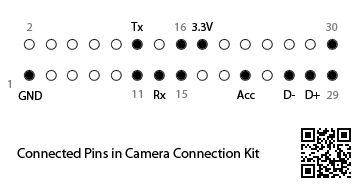
With the first generation iPad, Apple released the Camera Connection Kit, which is similar to what the iPod Camera Kit offered, but better. It comes with 2 separate dongles - one with a SD card slot, another with a USB female port. The 3.3 V accessory power has been stepped up to provide 5 V for the USB device. If you’d like to take a peek inside, iFixit has posted a teardown of the SD card adapter and flickr user endolith has posted the innards of the USB adapter.
From both sets of photos, the connected pins can be mapped. Both adapters use the same set of pins. The serial pins, 3.3 V accessory power, as well as D+ and D- of USB are used for the Camera Connection Kit. Similar to the video out accessory mentioned above, the serial pins are used to perform protocol negotiation as well as authentication. Since the USB data pins are passed through, it is assumed that the iPad will internally switch to host mode. iAP over USB is not used here probably due to the complexity of trying to share the USB data bus with the connected USB device.
Apple also released a Digital AV Adapter which outputs HDMI, including audio. No one has done a teardown of this device yet, but I believe it is not a simple pass-through as even the clones of it are quite bulky, hinting the presence of some conversion circuitry.
Device Charging
Charging iPods used to be a simple affair, until the iOS devices came out. In fact, it still is. Charging is a very basic function and requires no authentication chip of any kind. In the earlier iPods, the accessory detect pin was used to identify different accessories, such as docks and vehicle connectors, and therefore changed the charging behaviour of the device (for example, continue powering the iPod after charging is complete). There were other pins that were used as a sort of “accessory detect” pin as well which affected charging behaviour.
Limor Fried (ladyada) reverse-engineered the Apple charger for iOS devices when she needed to make the MintyBoost work with iOS devices:
We thought “is there a enumeration chip inside every charger?” but since thats expensive and kind of overkilly we decided instead to read up on the USB protocol (go Jan!). […] we figured that we should see if there was some sort of special state you could put the data lines into that would say “no computer is attached but there is power”. Turns out there is! Its called the SEI and occurs when BOTH data lines are at 3 V.
This worked fine until the iPhone 3G came out, which had the dreaded “Charging is not supported with this accessory” message. Turns out that Apple used the USB data lines to indicate the amount of current that the charger was capable of providing:
We redesigned the PCB to allow us to have 4 resistors on the datalines and put two 75 K and two 49.9 K resistors in each kit. So far we have had no problems charging any of the latest Apple devices. Hooray!
Today, the iPad requires a 2 A charger whereas the iPhone ships with a 1 A one. The same “protocol” is still used to distinguish between the two.
A New Dock Connector?
There has been rumours of the next iPhone sporting a more compact dock connector. I wouldn’t be surprised, given the amount of legacy cruft that has been accumulated.
If I had to guess, they would keep USB (duh), audio out, accessory power (3.3 V and/or 5 V), and maybe the serial pins if they want to keep USB pass-through functionality simple and yet be able to perform MFi authentication certification. They could drop the audio in/out pins if they opt to carry the data over USB instead. A side-effect of this is there won’t be any “simple” docks any more and the price of docks with line out capability will significantly increase.
The analog video output would probably be replaced by HDMI, so in the future a bulky external adapter may not even be needed (by this I mean it could be a simple cable with no conversion circuitry). And of course there should be room for future expansion.
Apple has done a pretty good job of keeping the same connector for close to 10 years. What kind of decisions will they make for a new connector to last another decade?
Update 14-Nov-2012: Added a section on Device Charging.