Circular Layout ULP for Eagle
Some time last year, Mats Engstrom shared his PHP script for generating commands to move components in CadSoft Eagle to form a perfect circle. If you look at the screenshot, it’s mainly made up of MOVE and ROTATE commands - relatively easy.
Eagle has what it calls user language programs (ULPs) for doing some simple scripting with the ability to display a dialog for user input. I decided to try my hand at creating a ULP that creates these circular layouts. The main advantage of using a ULP is that it has access to your board layout, saving you from some typing. You can also easily iterate through different parameters quickly and without hassle.
I shall illustrate briefly how this circular layout ULP can be used for doing various kinds of layout, with help from some open-source projects with Eagle CAD files.
Ringo3 Clock
The most common use for a circular layout is in clocks. Conveniently, Mats has a project called Ringo3. For photos of the PCB and assembled clock, see this Dangerous Prototypes forum topic.
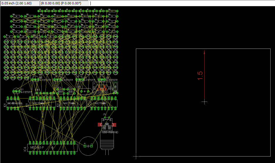
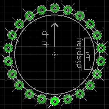
Delete the existing board (.brd) file to start with an empty PCB created from the schematic. We shall take (2.00, 1.60) to be the centre of the circle, as shown. Eagle 6 introduced a dimensioning tool, used here to show the radius of the circle (1.5") - handy but not a must.
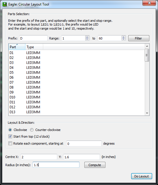
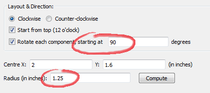
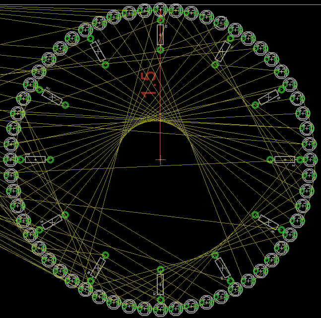
The circular layout ULP has 3 main sections: (i) parts selection, (ii) layout options, and (iii) circle centre point & radius. For parts, enter D for prefix and 1 to 60 and click the Filter button to select components D1 - D60 for layout. The handy table shows you the currently selected list of components. Enter 2 and 1.6 for the circle centre X, Y values that have been identified. The radius has been marked by the dimensioning tool as 1.5. The layout direction is “Clockwise” and we want to place D1 at the top “12 o’clock” position. Click the Do Layout button, and OK to start the layout.
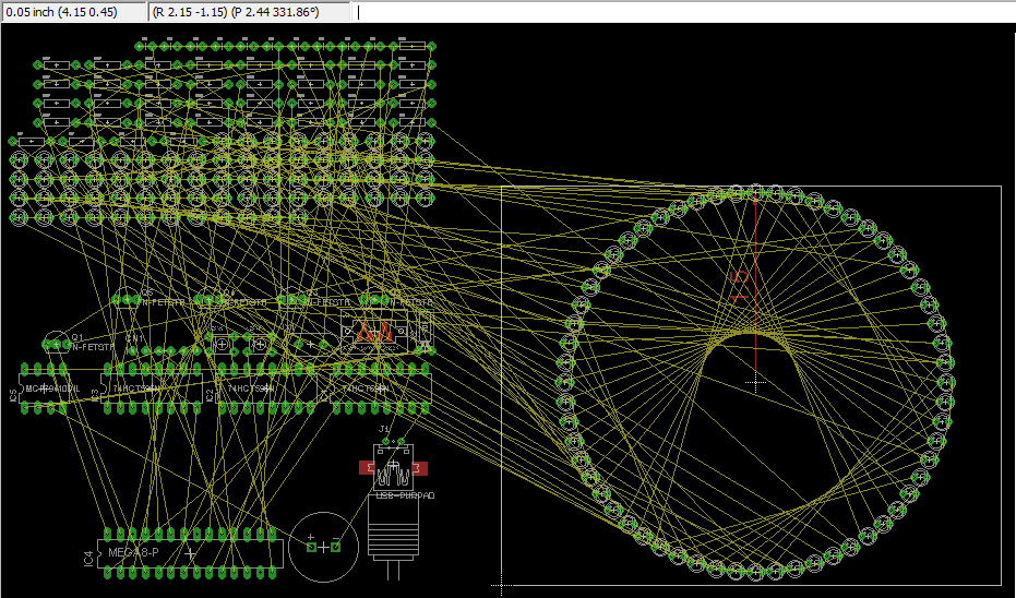
You should see the components move into place as shown in the next figure.
If you make a mistake, you can always just hit Undo or hold down Ctrl+Z until all the components were back at their original positions.
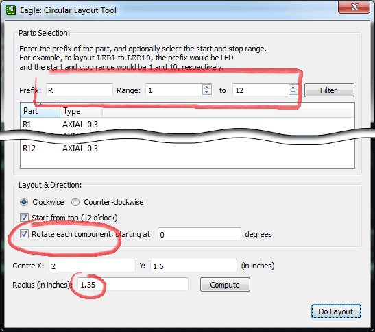
You might also want to place the resistors close to the LEDs, so we shall try that next. From the schematic, we can see that every group of 5 LEDs share 1 resistor, so we shall layout R1 - R12 for these LEDs. All the settings will be the same as before, but we want the radius to be smaller (1.35" this time). We shall check the “Rotate each component” option, but leave the angle offset box at 0 degrees (we’ll talk about that shortly).
You should see the following result.
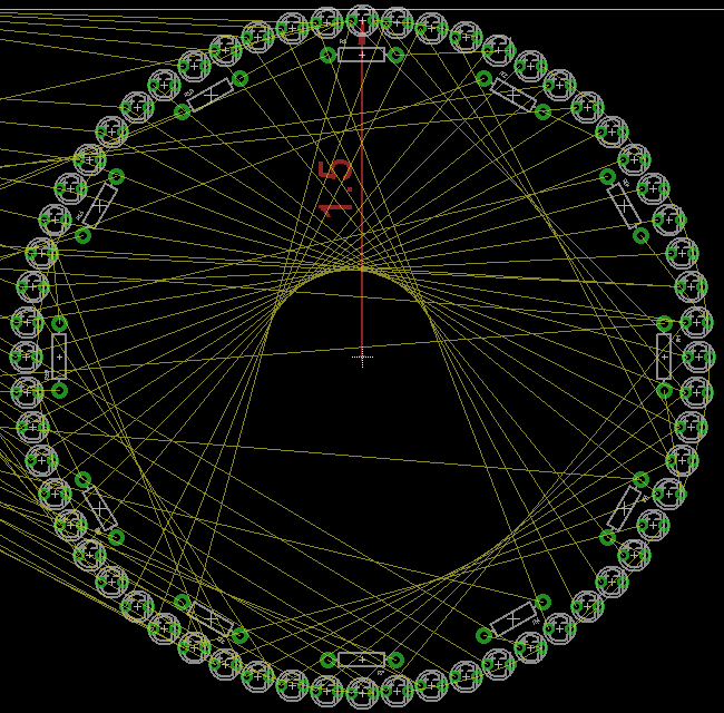
If instead we want the resistors to point outwards (or inwards), the angle offset should be changed to 90 degrees to orient R1 in the 90-degree position. Since the resistors now take up more space, we should also reduce the radius accordingly to 1.25".
This is the basic circular layout, but wait, there’s more!
Ice Tube Clock
Adafruit carries what it calls the Ice Tube Clock. The circular layout ULP works for Eagle footprints too. You can see that the footprint for the tube isn’t a perfect circle - a circle was drawn to (I guess) guide the placement of the pads (or holes, rather), but it also shows that the pads are not equidistant from the circle.
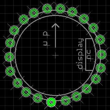
In this case, we want as little change as possible to the layout. By unchecking the “Start from top” option, the ULP will calculate the position of the pads as usual, but will now try to locate the position closest to the first pad and start there. This option tells the ULP that you have already roughly placed the first component and you want it to start there. At this point, you can also hit the Compute button for the “Radius” field to calculate the distance of the first component from the circle centre. Note that for footprints, Eagle would prefer your part to be around the center point (0, 0), so you didn’t have to fill in the circle centre X, Y coordinates.
Notice the new position of pin #1. To highlight the pin 1, just type SHOW 1 in the command bar, just above the layout window. You should see the pin highlighted, like in the screenshots.
If you think the circle is too small, you can just move pin 1 further outwards, launch the circular layout ULP, and hit the “Calculate” button to detect the new radius, then hit the Do Layout button to make the circle larger.
Download, Use, Modify
These are the scenarios which I use the circular layout for and there may be others I haven’t thought of, or needed. Feel free to use this ULP for laying out your boards, or modifying it to suit your needs.
To start using it, you can download the ULP from my Bitbucket repository.