This challenge exposes a service written in PHP, and as you can guess, it has something to do with unserialization.
The single source file is straightforward to understand:
<?php

$line = trim(fgets(STDIN));

$flag = file_get_contents('/flag');

class B {
  function __destruct() {
    global $flag;
    echo $flag;
  }
}

$a = @unserialize($line);

throw new Exception('Well that was unexpected…');

echo $a;
Your goal is to get the flag printed by somehow getting the destructor of class B to execute.
Written by Darell Tan on 28 Dec 2018Share Comments
Following up from my earlier post, Asus has released faster and beefier routers. But perhaps the more important change here is that they have moved from MIPS in the RT-N56U to ARM in newer routers. I have also upgraded to the RT-AC68U for better reception and hopefully to fix the poor battery life experienced by my Android tablet.
After upgrading, I noticed that the method I described back then no longer works. Someone also noticed this, as they translated key portions of my post into Chinese, while pointing out some of the steps that didn’t work.
In this post, I’ll summarize the key changes required to get it working again.
Written by Darell Tan on 22 Jul 2018Share Comments
I bought a Banana Pi some time ago and have been using it as my go-to ARM box. Among the single-board computers I have, this Allwinner A20-based platform has the fastest CPU.
Similar to the (old) Raspberry Pi, it has a 26-pin GPIO header on one side that sports the same layout. This means that the 5 V, 3V3 and I2C pins are the same as where they would be on the Raspberry Pi.
Device Tree & Overlays
On embedded systems, the Device Tree helps the kernel understand various peripherals that are connected to the board and how to initialize them. These hardware might be things like LDO regulators, various controllers, GPIO, etc which are generic, but yet needs certain configuration that should not be hard-coded into the kernel. To understand more about device trees I recommend you start with the Raspberry Pi documentation on this topic. There are more links at the end of this article.
To support Pi HATs and other non-HAT accessories, the Pi added a dtoverlay configuration parameter in the config.txt file. This allows you to specify, at boot time, Device Tree Overlays, which modify the board’s base device tree to specify additional peripherals like I2C devices, or to configure GPIO pins for certain purposes. The BeagleBone also has a similar mechanism to support its add-on boards via Capemgr. These mechanisms enable non-technical users to easily modify the device tree by simply editing a text file or running a command. Neither of these have been adopted into mainline Linux, so there is no provisions for doing quick overlays on other boards yet.
Fortunately for us, device tree overlay support has been merged into U-Boot, and the Banana Pi uses U-Boot for booting Linux. This means that U-Boot can perform the merging of device tree overlays with the base device tree, and pass the entire Flattened Device Tree (FDT) structure to the kernel during boot-up.
Before we get started, you will need the i2c-tools and dtc-overlay package, and the U-Boot source code for the mkimage tool (you did have to compile U-Boot for your Banana Pi right?)
Creating the Overlay
For this example, we will be attaching an INA219 current sensor to the Banana Pi over I2C. The kernel has drivers for this sensor in its hwmon subsystem and provides an easy way of reading values for us.
The default I2C address on most INA219 breakout boards is with the address lines A0 and A1 grounded, giving it an address of 0x40. Also note that the shunt resistor is marked with R100, which denotes 0.1 mΩ or 100,000 µΩ.
We will try scanning each of the buses, and the one with device 0x40 will likely be the bus that is exposed via the GPIO headers. We can do this using i2cdetect:
The last parameter to i2cdetect specifies the bus number, which is 1 in this case. We can see here that the INA219 has been correctly wired and detected, as it shows up in the I2C bus scan.
We now need to find out which device tree node this bus corresponds to:
I have been looking around for Power over Ethernet (PoE) devices to supply power to some networking hardware that will be located in a remote location, without a convenient power outlet. These networking hardware do not have built-in PoE support, so I have to find both an injector and a splitter device.
PoE is typically found on enterprise networking equipment, which usually means a higher price tag. Not wanting to spend a ton on PoE hardware, I did some research to understand what was required to make it work.
Hopefully this will help you understand PoE, how it works, and what to look out for when shopping for PoE hardware that are suitable for your needs.
PoE Quick Guide
Active vs Passive
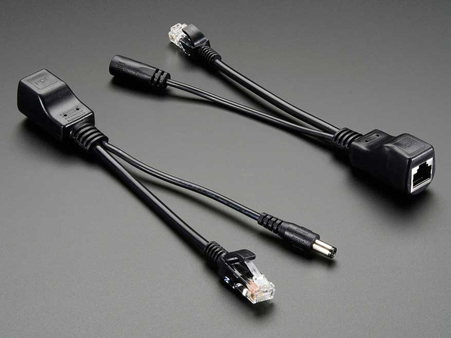
Passive adapters are very simple, and you will see them mostly as an RJ45 socket with pigtails for power and Ethernet. These adapters do not contain or require any circuitry, which also explains why they are the more inexpensive option between the two.
Active PoE (the real Power over Ethernet) on the other hand requires some negotiation between the two devices, called the PSE (power sourcing equipment) and the PD (powered device).
There are several PoE standards. 802.3af, 802.3at and the newer 802.3bt. The difference is mainly in the maximum power is made available to PDs:
802.3af - 15.4 W
802.3at - 30 W
802.3bt - 60 W to 100 W
802.3bt was just ratified in the last year (2017). In the time span before the 802.3bt standards was ratified (~8 years!), some companies like Linear Technolgy & Cisco Systems took it upon themselves to find other means of carrying up to 60 W. The result was LTPoE++ and UPOE, an evolution of the existing 802.3af/at standards, but may not be compatible with the final standard arrived at by committee.
Mode A or B
The Cat5 cable has 8 wires, forming 4 twisted pairs. For 10/100 Mbps, only 2 pairs are used: pair 1/2 for Tx and pair 3/6 for Rx.
The modes refer to how power is delivered to the device:
Mode A: pairs 1/2, 3/6
Mode B: pairs 4/5, 7/8
Mode A uses the data pairs for power. This mode is well suited for very old cabling which didn’t connect all 4 pairs end-to-end. You might see some manufacturers calling this mode End-span wiring. To carry power over the same data cables, phantom power delivery is used (more on this later).
Mode B uses the unused (or spare) pairs for power. You might see this being referred to as Mid-span. This type of wiring is easier because it knows the pair is not carrying any data and thus can be wired directly.
Unlike mode A, mode B in this form cannot be used to carry power for Gigabit networks, because a Gigabit connection will require all 4 pairs for data transmission. Power must therefore be delivered via centre-tapped transformers, or what is known as phantom power. How this works is explained in a 1944 US Army video on telephone electronics.
Power Capacity
The committee decided that two pairs of Cat5 wire should only carry up to 30 W of power; which two pairs will depend on whether mode A or B wiring is used.
For higher power capacity like 802.3bt (PoE++) or the non-standards-based UPOE and LTPoE++, the other 2 pairs will be paralleled up, making use of all 4 pairs to carry higher currents.
For Gigabit Ethernet (1000 Mbps), because all 4 pairs are used to carry data, power (regardless of which pairs used) must be delivered via phantom power delivery.
Why use Active PoE?
In short, because it is safer.
It was designed with the consideration that not all network equipment can accept power, whether via the data pairs or spare pairs.
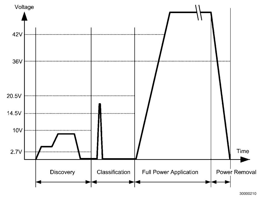
During the detection phase, the PSE will apply 2.7 V to 10 V to check for a known resistance. This voltage is low enogh and also for a brief period such that it wouldn’t matter if the device on the other end is shorted. A device that was not designed for PoE would thus never see any higher voltage beyond the detection phase.
In contrast, passive PoE makes the full voltage and current available on the data/spare pairs. If the remote end is using a magnetics configuration that shorts out the centre taps, the 30 W of power would just melt the port (one would assume).
Integrated PSE controller chipsets will also contain features like overcurrent protection, thermal cut-offs and surge protection, etc. which all contribute towards keeping your PDs safe from harm.
Finding Low-Cost PoE Hardware
It was quite a daunting task, trawling AliExpress for PoE injectors & splitters. The description or specifications for items are also not accurate; it’s like finding a USB cable listed as capable of carrying 2 A when in fact it does not.
While passive injectors are the cheapest option, most of them are not meant for Gigabit Ethernet. Recall that Mode B wiring is the easiest and most low-cost method for building a passive device, and that is what you will mostly find. This wiring configuration does not pass through all 4 pairs and thus cannot be used for Gigabit.
Most active PoE splitters output 12 V, or 5 V via USB. This is largely due to the fact that these devices were meant for IP cameras, which operate at that voltage. If your target device uses a non-standard voltage, you will have difficulty finding a suitable (and yet low-cost) splitter.
Here’s a list of hardware I’ve found; which one is suitable for you depends on your requirements:
Do you need 1000 Mbps, or just 10/100 Mbps would suffice?
Written by Darell Tan on 10 May 2018Share Comments
These days with larger and larger drive capacities, erasing stored data takes longer and longer. Another problem is also the inability to do so when the time comes, due to bad sectors or hardware failures. Just because the data is not accessible by you does not mean that it is also inaccessible to someone else with the know-how.
Cryptographic erasure to the rescue!
Crypto erase simply erases the encryption key that is used to encrypt the data on your drive. This is the primary reason why I encrypt my drives.
But what if we are not running Windows? What if the disk is not a Windows boot drive that is protected by a TPM key protector?
In order to erase the (key) data, we first need to know how the data is stored on disk. For open-source FDE implementations, this is easy because the disk format is well-documented, but BitLocker is not exactly open.
BitLocker Disk Format
BitLocker was first introduced in Windows Vista and has gone through changes since then. Some changes were made to the format in Windows 7, but has largely remained unchanged through Windows 8 till 10.
For LUKS, it is simple - there is a LUKS header at the start of the disk, followed by the encrypted volume data. For BitLocker, it is slightly more involved, probably due to backward-compatible design considerations.
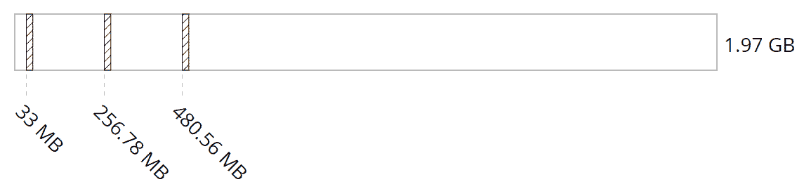
The header at the start of the partition is a valid boot sector (or boot block), so not all BitLocker information can be stored within. Instead, this volume header points to the FVE metadata block where most of the data is kept. In fact, there are 3 of these for redundancy. This metadata block is what holds all the key material.
The metadata blocks are spaced (almost) evenly apart, located near the start of the volume.
PCBWay is a PCB manufacturer that prides itself on quick turnaround. You can learn about CNLohr’s sucess story here. They also offer detailed tracking of your order’s progress on their website.
They have reached out to me and kindly offered to sponsor the boards for this particular project, which I will be talking about in the coming weeks. As the cost of these boards were more expensive (compared to their “normal” orders), I had to pay for shipping myself.
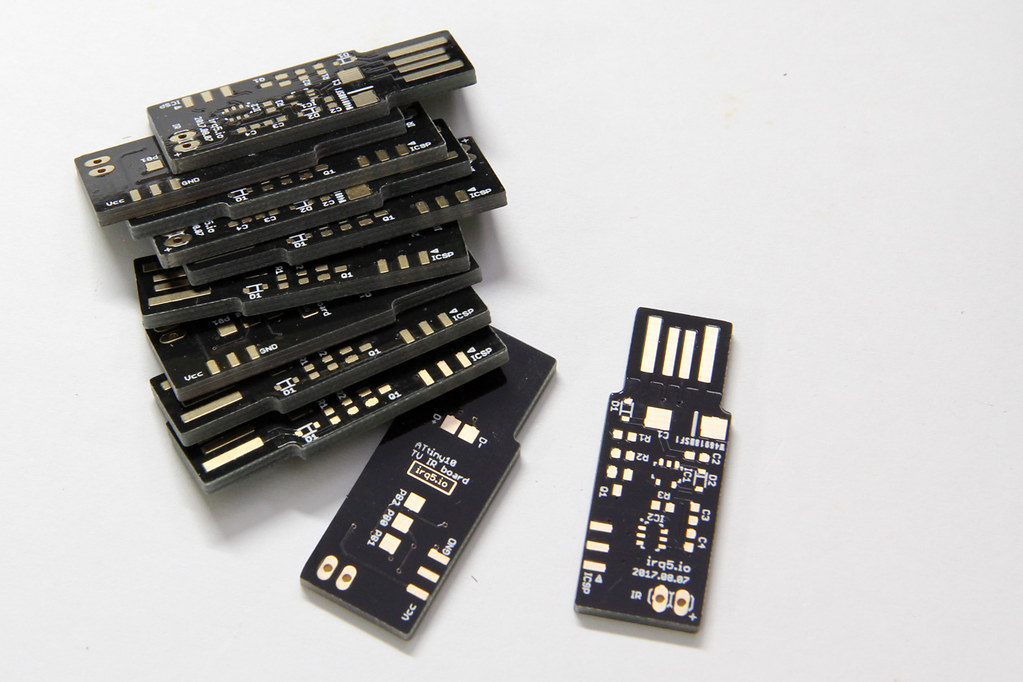
With each PCB project, I find more and more methods of testing PCB manufacturers. This time, it’s with a PCB that is inserted directly into your USB socket.
The requirement for such a board is 2 mm thickness. The USB connector size is standard, so the usual 1.6 mm PCB thickness isn’t going to work unless you pad the connector area.
Also, I opted for gold fingers on the USB connector contacts. This is usually done for contacts on the board edge that will be inserted into some mating connector (like PCI cards and USB connectors such as this).
They also offer matte black & matte green colors. I haven’t seen matte colours being offered at other board houses so far. I would have loved to try them out, but that would have bloated the cost beyond my comfort level.
Order Process
The order flow for PCBWay is a bit different because you submit your gerbers without making payment first. This allows their engineers to take a look at the design before you actually pay.
Most other systems I’ve used are largely automated. After you submit your gerbers, they typically don’t expect any problems and so they collect payment from you first.
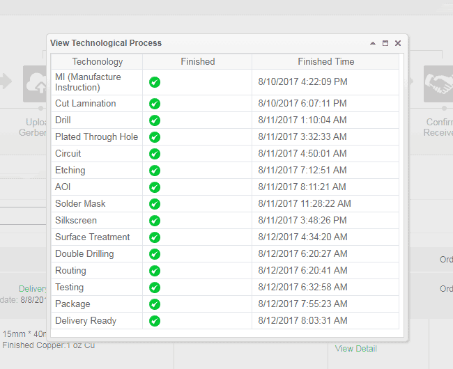
I uploaded the gerbers on the 8th Aug and I tracked my order progress online. Their website allows you to track the detailed progress of your board as it moves along the manufacturing process. For small runs like this one, it is not crucial but if you were doing a large project with panels of many boards, this would definitely be handy.
They started manufacture 2 days later (on the 10th) and completed everything by 12th. It was not until the 14th that they actually shipped the boards out and provided me with a tracking number.
Written by Darell Tan on 14 Oct 2017Share Comments
Flare-On 2017 Challenge #5 – pewpewboat.exe
As usual, the first thing to do when tackling the challenge is to run the binary first, to see what it does. You will soon learn that it’s not actually a Windows executable, but rather a 64-bit Linux ELF.
$ ./pewpewboat.exe
Loading first pew pew map...
   1 2 3 4 5 6 7 8
  _________________
A |_|_|_|_|_|_|_|_|
B |_|_|_|_|_|_|_|_|
C |_|_|_|_|_|_|_|_|
D |_|_|_|_|_|_|_|_|
E |_|_|_|_|_|_|_|_|
F |_|_|_|_|_|_|_|_|
G |_|_|_|_|_|_|_|_|
H |_|_|_|_|_|_|_|_|

Rank: Seaman Recruit

Welcome to pewpewboat! We just loaded a pew pew map, start shootin'!

Enter a coordinate:
So this is a Battleship game. Playing manually for a bit, I see the “ships” form up in the shape what looked like a letter. Hmm could this be the flag?
I previously wrote about the hardware aspects of getting your code into an ATtiny10 some 7 years ago (wow that was realllyy a long time ago!).
Now, avrdude is at version 6.3 and the TPI bitbang implementation has already been integrated in. The upstream avr-gcc (and avr-libc) also have proper support for ATtiny10s now. These software components are bundled with most distributions, including the Arduino IDE, making it easily accessible for anyone. Previously a fully integrated and working toolchain only came from Atmel and it was behind a registration page.
The price of the ATtiny10 has also dropped by a lot. When I first bought this microcontroller in 2010, element14 carried it for $1.85 in single quantities. Now, they are only $0.56 each.
I thought I’d write up a short post about writing and compiling code for it.
Written by Darell Tan on 30 Aug 2017Share Comments
When writing a bruteforcer, it’s easiest to think of it as mapping some kind of output to a monotonically-increasing number.
Like for one of the solved PlaidCTF question, the answer string was composed from the eight letters “plaidctf”, which conveniently is a power of 2, meaning each output character can be represented with 3 bits. To write a bruteforcer for a string composed of these characters, you might imagine generating a 3-bit number (i.e. from 0 to 7) then mapping it to the character set for one output character, or a 30-bit number if the output string was 10 characters. Unsurprisingly, this was exactly what I did for my solver script. The output string was generated from a BitVector of 171 * 3 bits.
But what if the output was composed of several different pieces that cannot be represented uniformly as a set of bits?
One solution might be to emulate such a behaviour using an array of integers, like how I modified my solver script in version 2 to handle a character set of arbitrary length.
In this post, I will walk-through writing a basic, but flexible, bruteforcer with accompanying code snippets in Go.
Keeping State
Continuing on the CTF puzzle, the BitVector was replaced with an array of Ints. Each Int will represent one character of the output string. We can thus represent the state like so (for simplicity, let’s limit the output string to 2 characters):
typestatestruct{digit[2]int}
In order to increment each digit, we can write a function that increments state.digit until a certain number, then resets it to zero.
To make it generic, we will write a function that returns another function that manipulates a digit position, so we don’t have to copy & paste the code for each digit position:
// returns a function that manipulates the digit at given pos
funcdigitManipulator(posint)func(*state)bool{returnfunc(s*state)bool{s.digit[pos]++ifs.digit[pos]==MAX_NUMBER{s.digit[pos]=0returntrue}returnfalse}}
We will talk more about the boolean return value later.
Written by Darell Tan on 27 Jul 2017Share Comments
Hint: Send me this identifier together with your $$$$ to decrypt your file: da91e949f4c2e814f811fbadb3c195b8 Binary4 is a Mach-O binary, nothing IDA Pro can’t handle. You will notice it has some obfuscated names, like wshwfknafsknfadj, pojklfasd, etc. Looking at the main() function, IDA Pro’s decompiler produces the following pseudo-C code: memset(&v17, 0, 0x400uLL); v17 = 46; LODWORD(v3) = wshwfknafsknfadj(&v17, 0LL); v15 = v3; LODWORD(v4) = bmasdfiukjwe(&v17); v14 = v4; if ( 999 !