Written by Darell Tan on 27 Jul 2017Share Comments
Mobile track #1 - EzDroid Provided is an Android app package EzDroid.apk. I typically use an Android emulator for testing, it’s free and easy to install on all major platforms, so it’s pretty much a no brainer. After installation, it looks like it maanges to start but exits shortly after, for some unknown reason. Looks like it is time to inspect the code. I like looking at high-level languages, so let’s start with that first.
Recently, I thought I’d get one because doing a re-programming cycle is taking quite a bit of time (a disadvantage of serial port bitbanging).
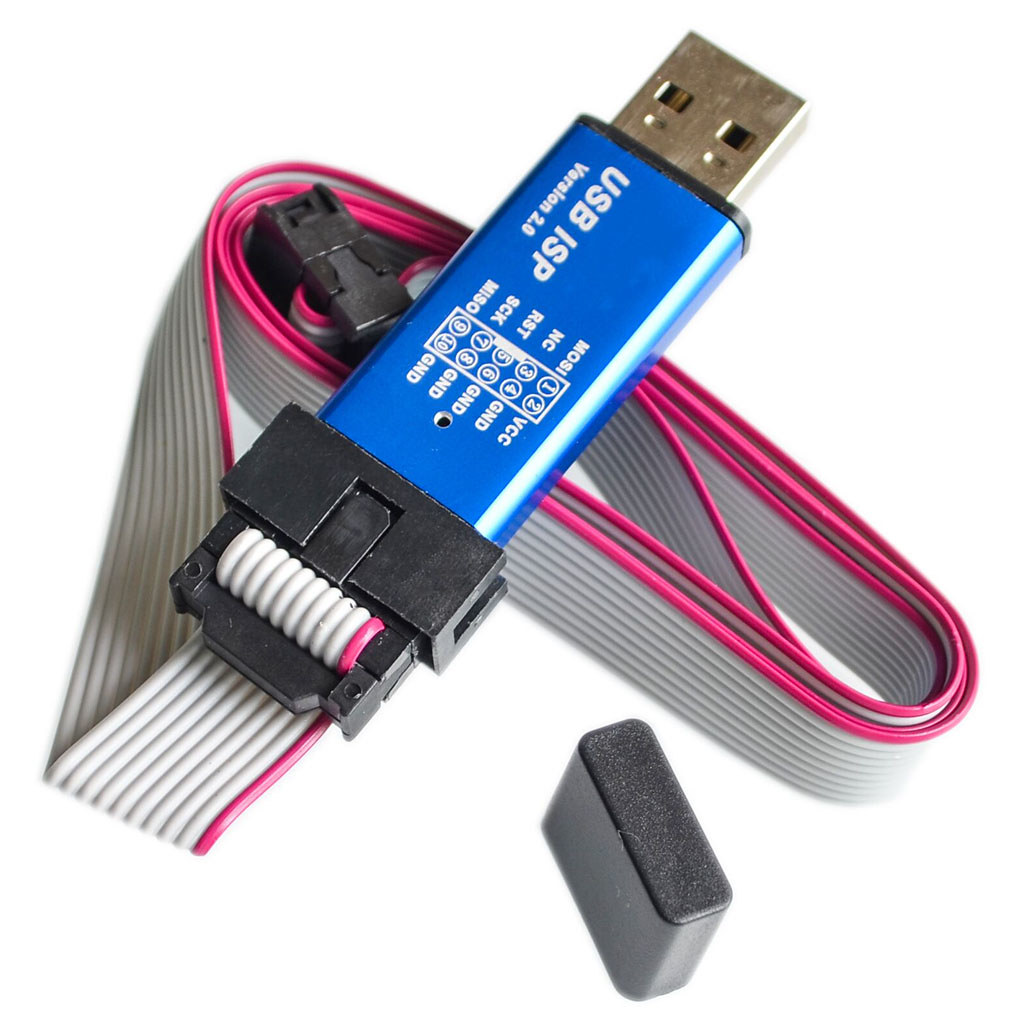
A popular one on Aliexpress seems to be this “USB ISP” one, so I bought one. I chose this one because it has a nice aluminium case, and a pinout diagram imprinted on the case, which is handy. After having so many one-off projects with bare PCBs collecting dust, I now appreciate the importance of having projects in their own box or case.
While it has “USBasp” in the item name, it turns out that this was not a USBasp device, and getting it to work like one takes some effort.
It identifies itself as a zhifengsoft HID device when I plug it into Linux:
[705621.968025] usb 3-1: new low-speed USB device number 3 using ohci-platform
[705622.199065] usb 3-1: New USB device found, idVendor=03eb, idProduct=c8b4
[705622.205939] usb 3-1: New USB device strings: Mfr=1, Product=2, SerialNumber=0
[705622.213194] usb 3-1: Product: USBHID
[705622.216876] usb 3-1: Manufacturer: zhifengsoft
avrdude does not recognize the device, even after creating an entry with the corresponding vendor/product ID. This particular device was designed to work with their Windows-based UI called ProgISP and will not work with avrdude.
And apparently you can’t just take the USBasp firmware and flash it into this device, because the circuit is somewhat different.
After some research based on the PCB markings, I found these sites that talk about them:
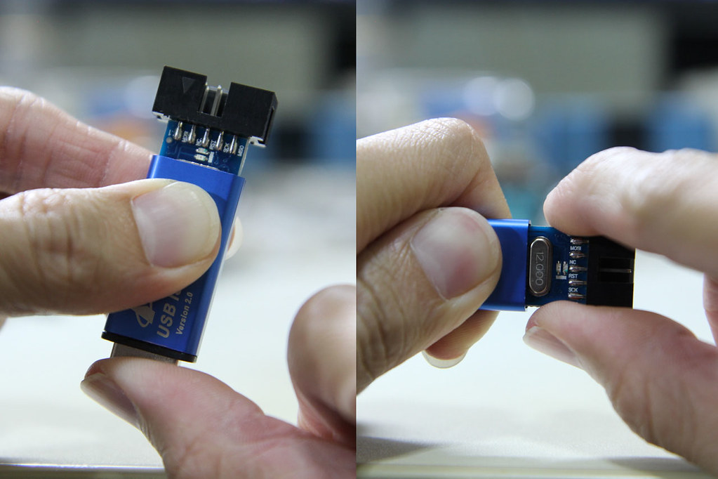
Disassembling the device is simple. While grabbing the side of the case, firmly push the USB connector inwards and the board should slide out the other end. You can then gently pull the board out by the IDC connector.
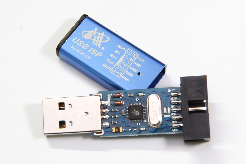
The programmer seems to be based off of the popular USBasp programmer, but modified somewhat (to what end I’m not sure). It lacks some features offered by other USBasp programmers, like the ability to control the target’s clock, or to use 3.3 V for certain targets. But at $2 with a nice aluminium case, what more can you ask for?
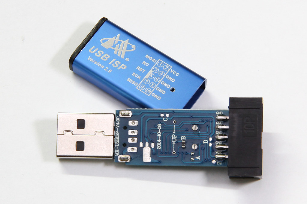
It’s powered by an ATmega88 (I read that older versions were based on ATmega8). The markings on the board indicate that this is a MX-USBISP-V4.00. You can ignore tHe date because it was never updated; the older V3.02 also has the same date. While the GreenPhotons blog was talking about V3.00, I have verified that this version suffers from the same issue.
Note that there are provisions on the PCB to add a voltage regulator, and the PCB link marked “C” can be cut to separate USB power from the rest of the system. Link “D” can be cut if you wish to disable target power. However, none of these options were used.
The crucial difference with this clone is that the USB D- pin is additionally connected to PD3, shown here highlighted in blue:
However, in the USBasp’s main() function, PORTD’s data direction register was initialized like so:
/* all outputs except PD2 = INT0 */DDRD=~(1<<2);
This causes the USB D- line to be actively driven from PD3, thereby impeding communication to/from the USB host.
The rest of this post will talk about (1) correcting this problem in USBasp, and (2) uploading the firmware into your zhifengsoft programmer.
Written by Darell Tan on 11 Jul 2017Share Comments
I have been running a software RAID array at home for some time now. It’s a single network storage where I consolidate all my files. I manage this array manually using the mdadm command. Some people choose to buy a NAS storage box which hides all of the implementation details behind a nice Web GUI, but it’s essentially the same thing under the hood.
It operates with 4 drives using Linux software RAID 5, which means it can tolerate a single drive failure, but failures don’t always take out an entire drive. They usually manifest as bad sectors in a drive. As an illustration, the RAID 5 array below can still operate properly (meaning no data loss, yet) with bad sectors on two of its drives:
As long as the other drives in the array doesn’t develop bad sectors in the same stripe, the data can still be reconstructed from the remaining good blocks. This means that you can somewhat leave the drive as it is for a period without replacement, but of course you are taking a risk.
I thought I’d share my experiences with drive replacements thus far.
Detecting Drive Problems
Most Linux distributions provide the raid-check script for periodic RAID scrubbing. This is basically a background cron job that tells the kernel to start checking the RAID array. For RHEL/CentOS systems, this should occur every weekend.
During this scrubbing process, all drives within the array are read and their parity blocks are computed, to ensure that everything tallies.
It is during this verification process that sometimes causes hard drive errors to show up. Typically when a drive encounters a problem during read, the hardware returns an error, which will then be logged by Linux. They can look like these:
Written by Darell Tan on 10 Mar 2017Share Comments
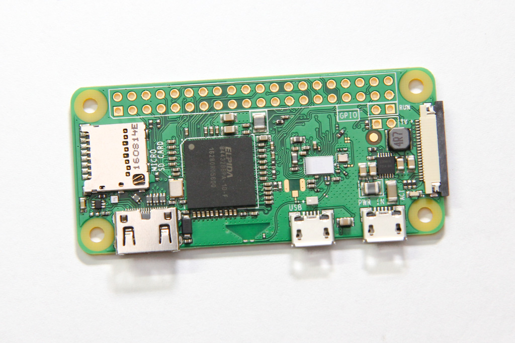
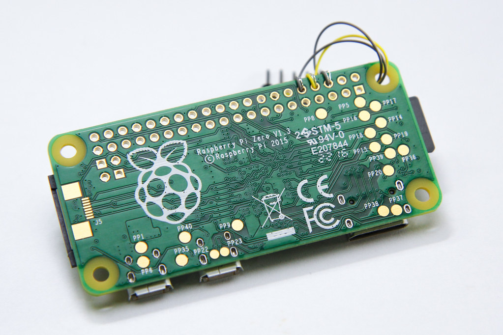
On the 5th birthday of the Raspberry Pi last week, the foundation announced a new addition to the family – the Raspberry Pi Zero W. The W stands for Wireless.
I got my hands on one, from the fine folks at Pimoroni. (And no they didn’t pay me to say this.)
It has the same specs as the Raspberry Pi Zero, namely the 1 GHz single-core CPU and 512 MB of RAM. It still has the two micro USB port – one for power and another for OTG, which means you can get it to behave like USB devices when plugged into a PC. The big difference is that they have added WiFi and Bluetooth capability to this small board by squeezing some space out from between the processor and the power circuitry. The size of the board and the placement of connectors remain the same, even the test points on the back.
I’m excited for anything that has processing power, HDMI connectivity and WiFi.
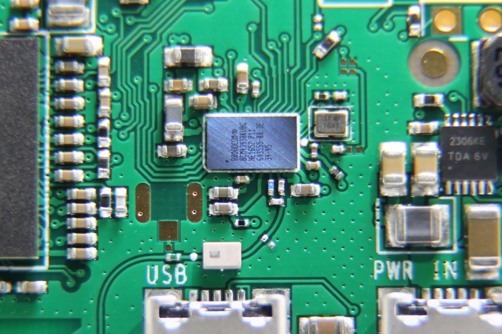
WiFi + Bluetooth
The 802.11n WiFi and Bluetooth 4.1 functionality comes from the Broadcom BCM43438 (now known as the Cypress CYW43438). This is the same chipset that was used in the Pi 3. The wireless chipset connects via SDIO, so your network traffic does not have to contend for the USB bus bandwidth.
This is only useful if the backup was encrypted by setting a backup password on the iOS device. If the backup is not encrypted then all the files are in clear and there is nothing to bruteforce.
The keys used to encrypt the backup are stored in the BackupKeyBag, which can be found in the Manifest.plist file. This keybag is a binary blob, the format of which has already been documented by researchers from Sogeti ESEC Lab.
iOS device backups usually take a while, depending on how much storage has been used on your device.
The iOS backup process is driven by the device itself, through the BackupAgent process. This process treats the host PC like a dumb disk store, by sending it commands like DLMessageCreateDirectory, DLMessageUploadFiles, DLMessageRemoveFiles, DLMessageGetFreeDiskSpace, etc. so that it can determine what has been backed up previously and what to send/update for incremental backups.
For password cracking, we don’t need the entire 64 GB (or God forbid, 128 GB) of data on the iOS device. We just need the Manifest.plist, which is typically less than 50 KB. But because the backup process is controlled by the device and not the PC, we can’t simply ask it to send over that single file. Sometimes when we setup a VM with libimobiledevice, we might also not have allocated such a large virtual disk. Of course when I say “we”, I really mean “I”.
Fusion PCB is a PCB service from Seeedstudio. They have been offering PCB prototyping service since I made my first board in 2011. It has recently been revamped a little, tweaking prices and options, as well as integrating an online Gerber viewer from EasyEDA. I was invited to give Seeedstudio’s revamped Fusion PCB service a try, and since I had some boards in the pipeline for manufacture, I thought why not?
You can configure various options for the PCB, such as board thickness, copper pour and surface finish. You can also make flex PCBs or aluminium for better heat sinking, as opposed to regular FR4. These options will of course come at a price. However, you can select various colours for your PCB at no additional cost.
The Boards
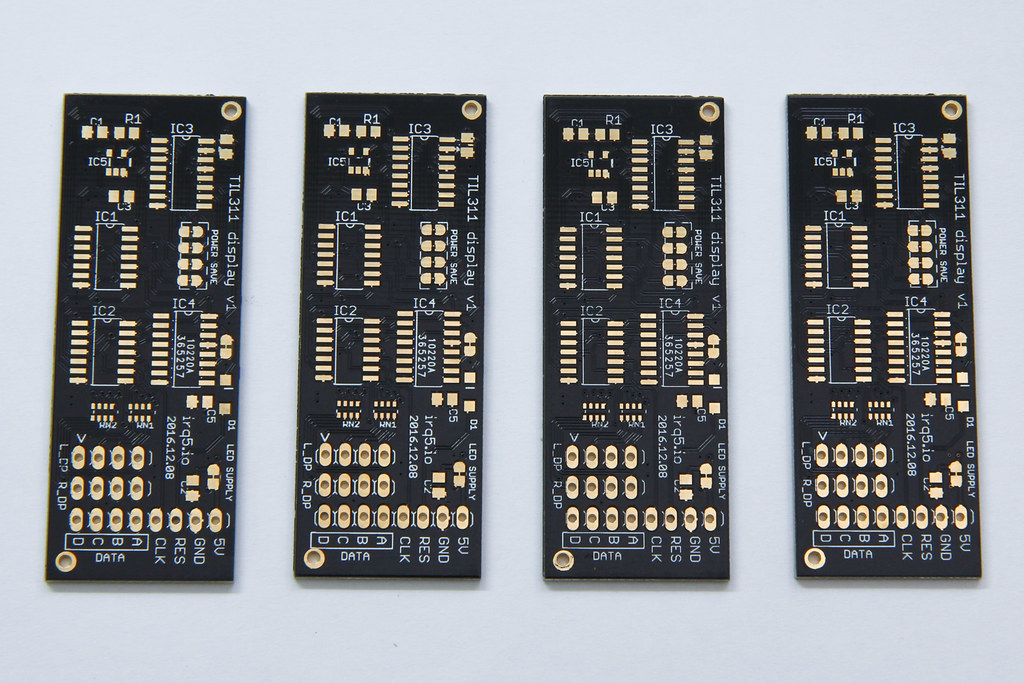
I ordered 2 sets of boards in total. I’ve decided to opt for an ENIG finish for the TIL311 display boards, just because it looks nicer in gold. The boards are manufactured with black solder mask, making the gold pads stand out better.
I’ll describe the display board in a separate post after I’ve assembled it. For now, here’s what 4 of the boards look like, component side up:
Like most PCB prototyping services, they track your order by printing some kind of order identifier onto each PCB. Usually they try to put this identifier underneath a component like an IC so it gets hidden when the board is fully populated, but sometimes they put it somewhere prominent, like under your product name. On this board, the identifier sits under IC4 but for the other board, it was under the product name.
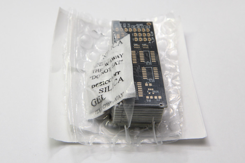
The PCBs arrived in a shrink-wrapped bubbly packaging to protect the boards. There was also a desiccant thrown in for one set of the boards to keep it dry.
Written by Darell Tan on 22 Dec 2016Share Comments
In case you haven’t heard, the Raspberry Pi Zero is the smallest, most low-cost device in the Raspberry Pi family, but it’s also the hardest to find. It has two Micro-B USB ports, one for power and another functions as a dual-role USB OTG port.
One of the more interesting uses for the Raspberry Pi Zero is to get it to behave as a USB device, just like your USB flash drive, for example.
There have been several guides written already, such as the Adafruit one, but most of them were based on the old kernel gadget drivers, like g_serial and g_ether. It still works, but not as flexible and likely to be deprecated in future.
Written by Darell Tan on 10 Oct 2016Share Comments
When I saw this post on Hackaday, I thought the display looks cool. Even the people who commented on the post thought so too. This board that you see in the post monitors the bus for the Z80 in the RC2014 retro Z80 computer kit.
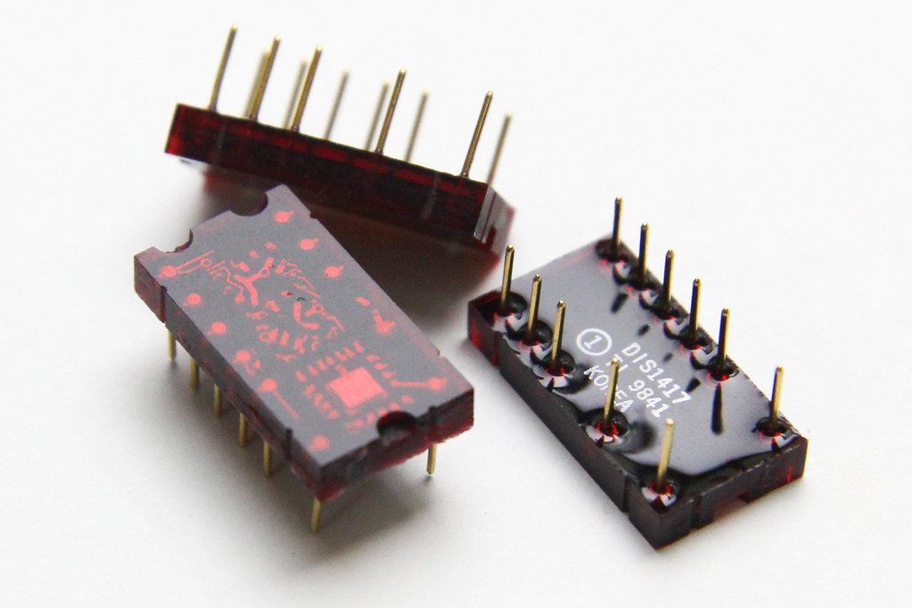
After some searching and the wisdom of the Hackaday crowd, I bought a few of them from eBay. It turns out that these displays are no longer being manufactured anymore. These used to be made by Texas Instruments, the TIL311 or DIS1417.
TIL311 / DIS1417 Displays
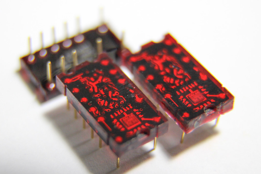
I like how the display looks like a pseudo LED matrix, forming a 7-segment display. They could have made the edges totally flat, just like a 7-segment display, but they chose to round the corners of certain digits and letters, like 0, 2, 8, A and others.
Each display has a built-in chip at the bottom of the digit, which you can see under bright lighting in close-up photos. The chip handles the latching and display logic, and contains a constant-current driver for all the LEDs to output a single hex digit (0-9, A-F). This was handy for old-school logic systems (like the Z80) because each display handles 4 bits, exactly a single hexadecimal digit. You could also interface this display easily without a microcontroller, as opposed to a display that that speaks I2C.
From the date code in the photos, you can that these displays were made in Korea in 1998. The pins look like they are made of gold, or gold-plated.
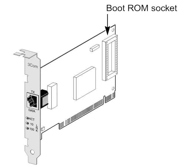
A very long time ago, I set up and played around with diskless machines. These are basically PCs can boot up an operating system fully without hard disks. All the operating system files come from a server on the network. It was amazing (well, to me at least)!
Back then, Ethernet cards used to have a DIP/PLCC socket, which allowed you to insert an EEPROM on which you burn a boot ROM. Fortunately I didn’t have to do any of that because the network cards at that time already came with PXE ROMs built-in, just as they do today. To activate this, you just need to select the network card’s option ROM in the boot order, or make it higher up in the boot priority.
As part of the boot process, the network card will request an address from the DHCP server, which also tells the client where it can find the TFTP server with the next boot stage. The ROM will download this file from the TFTP server and start executing it.
That’s how Linux ultimately gets started from the network.
An announcement was made recently on the Raspberry Pi blog that you can achieve total network boot, just like on the PC, without any SD cards.
Unix track #1 - bowie.pl This is a Perl script which is really large (3 MB). When you open it up, you’ll see it request input from STDIN, then compares it against these concatenated chars like so: my $input = <STDIN>; $input = trim($input); if ($input eq (chr(5156 - 5035) . chr(-4615 - -4716) . chr(3162 - 3047))) { ... It then has a lot of MIME::Base64::decode() statements, which seem to be building up data in variable $a.